Guide to the Arduino Mini
To get started with the Arduino Mini, follow the directions for the regular Arduino on your operating system (Windows, Mac OS X, Linux), with the following modifications:
- Connecting the Arduino Mini is a bit more complicated than a regular Arduino board (see below for instructions and photos).
- You need to select Arduino Mini from the Tools | Board menu of the Arduino environment.
- To upload a new sketch to the Arduino Mini, you need to press the reset button on the board immediately before pressing the upload button in the Arduino environment.
Information about the Arduino Mini
The microcontroller (an ATmega328) on the Arduino Mini is a physically smaller version of the chip on the USB Arduino boards, with the following small difference:
- There are two extra analog inputs on the Mini (8 total). Four of these, however, are not connected to the legs that come on the Arduino Mini, requiring you to solder wires to their holes to use them. Two of these unconnected pins are also used by the Wire library (I2C), meaning that its use will require soldering as well.
Also, the Arduino Mini is more fragile and easy to break than a regular Arduino board.
- Don't connect more than 9 volts to the +9V pin or reverse the power and ground pins of your power supply, or you might kill the ATmega328 on the Arduino Mini.
- You can't remove the ATmega328, so if you kill it, you need a new Mini.
Connecting the Arduino Mini
Here's a diagram of the pin layout of the Arduino Mini:
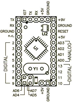 Mini 03 pinout (compatible with earlier revisions) |
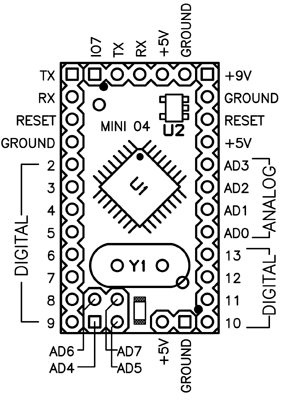 Mini 04 and 05 pinout (the ground on the left has moved down one pin) |
To use the Arduino Mini, you need to connect:
- Power. This can be a regulated +5V power source (e.g. from the +5V pin of the Mini USB Adapter or an Arduino NG) connected to the +5V pin of the Arduino Mini. Or, a +9V power source (e.g. a 9 volt battery) connected to the +9V pin of the Arduino Mini.
- Ground. One of the ground pins on the Arduino Mini must be connected to ground of the power source.
- TX/RX. These pins are used both for uploading new sketches to the board and communicating with a computer or other device.
- Reset. Whenever this pin is connected to ground, the Arduino Mini resets. You can wire it to a pushbutton, or connect it to +5V to prevent the Arduino Mini from resetting (except when it loses power). If you leave the reset pin unconnected, the Arduino Mini will reset randomly.
- An LED. While not technically necessary, connecting an LED to the Arduino Mini makes it easier to check if it's working. Pin 13 has a 1 KB resistor on it, so you can connect an LED to it directly between it and ground. When using another pin, you will need an external resistor.
You have a few options for connecting the board: the Mini USB Adapter, a regular Arduino board, or your own power supply and USB/Serial adapter.
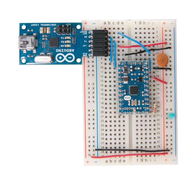
Connecting the Arduino Mini and Mini USB Adapter
The circuit shown here is the basic setup for an Arduino mini connected to a USB-to-serial converter. You can see power and ground from the USB are run to the rails of the breadboard so it's convenient for the other components on the board. The 0.1uF capacitor from the reset pin is connected to the RTS pin on the mini USB adaptor. This enables auto-reset when the serial port is opened, meaning you don't have to press the reset button every time you upload new code. If it gives you problems, you can remove it, and press reset every time.

You can use a USBSerial connector wired up in a similar fashion :
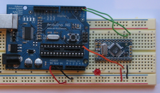
Connecting the Arduino Mini and a regular Arduino
Here's a photo of the Arduino Mini connected to an Arduino NG. The NG has its ATmega8 removed and is being used for its USB connection, power source, and reset button. Thus, you can reset the Arduino Mini just by pressing the button on the NG.
The text of the Arduino getting started guide is licensed under a Creative Commons Attribution-ShareAlike 3.0 License. Code samples in the guide are released into the public domain.